What Does Polarized Raman Imaging Actually Show You?
Orientation. A standard Raman spectrum tells you what a material is; polarized Raman tells you how it is arranged. For anything anisotropic, and that includes most crystals, layered materials, drawn polymers and stressed films, orientation is often the property that actually matters.
The physics in one paragraph
Raman modes have symmetry. How strongly a given mode scatters depends on the angle between the polarization of the incident light and the crystallographic or molecular axes of the sample. Rotate the polarization and the intensity of individual peaks rises and falls in a pattern that is characteristic of the material and its orientation. That angular pattern is the measurement.
What laboratories use it for
Crystal orientation and domain mapping. In 2D materials and thin films, polarized Raman distinguishes grains and domains that look identical in an unpolarized spectrum, which is how uniformity across a wafer gets assessed.
Stress and strain. Peak positions shift under strain, and the shift is direction-dependent. Polarization resolves the direction, not just the magnitude, which is what makes it useful for device reliability work.
Polymer chain alignment. Drawn fibres, films and packaging materials derive their mechanical properties from chain orientation. Polarized Raman measures it without destroying the sample.
Layer stacking. In stacked 2D materials the twist angle between layers changes electronic behaviour, and polarization-dependent modes are a practical way to read it.
Why the measurement is usually done badly
The physics is standard; the execution is where laboratories lose time. Done by hand, an angle-resolved measurement means rotating a polarizer or the sample stage, taking a spectrum, recording the angle, and repeating. A full 360° scan at reasonable resolution is dozens of manual steps for a single point. Multiply that by a map and the measurement stops being practical, so people take four angles instead of thirty-six and hope the interpolation holds.
Most polarization data is sparse not because the science needs it that way, but because collecting it by hand is tedious.
Automating the rotation changes what is realistic. When the instrument scans the full circle under software control, angle-resolved imaging becomes something you run routinely rather than something you plan a week around. Adding a second excitation wavelength on top of that lets you check whether an orientation effect is genuine or an artefact of resonance at one particular wavelength.
Practical questions to ask
- Is the polarization scan automated across the full 360°, and at what angular step?
- Can the scan be run per pixel across a map, or only at single points?
- If the system has two lasers, does the polarization scan run independently for each?
- How repeatable is the laser power between measurements? Intensity comparisons are meaningless if the power drifts.
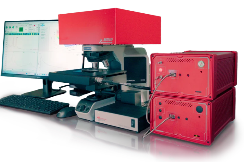
The MRID system we represent was designed around exactly this: two software-switched lasers, automated 360° angle-resolved polarized imaging for each, and laser power calibrated to under 1% error so intensity comparisons hold. Questions about your samples are welcome at info@rexerlab.com.